Energy & Carbon Modeling
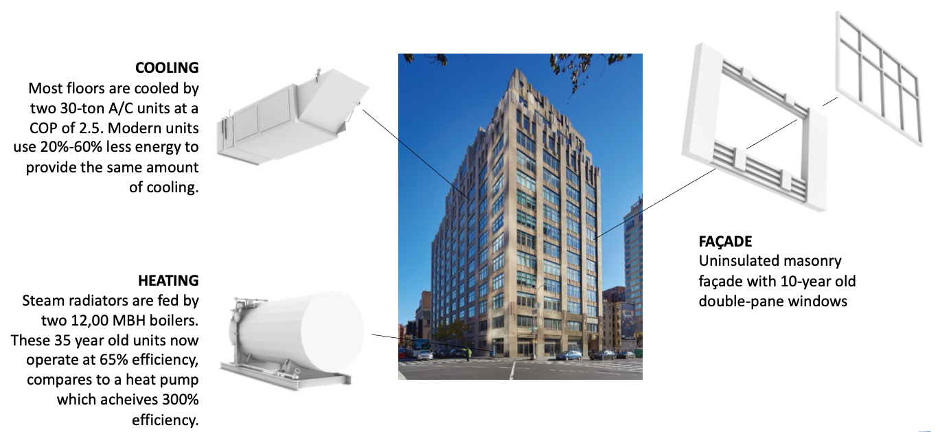
Back to Table of Contents Build and Calibrate the Initial Energy ModelThe project team created an energy model for 100 AoA which was calibrated using past year utility and operational data. 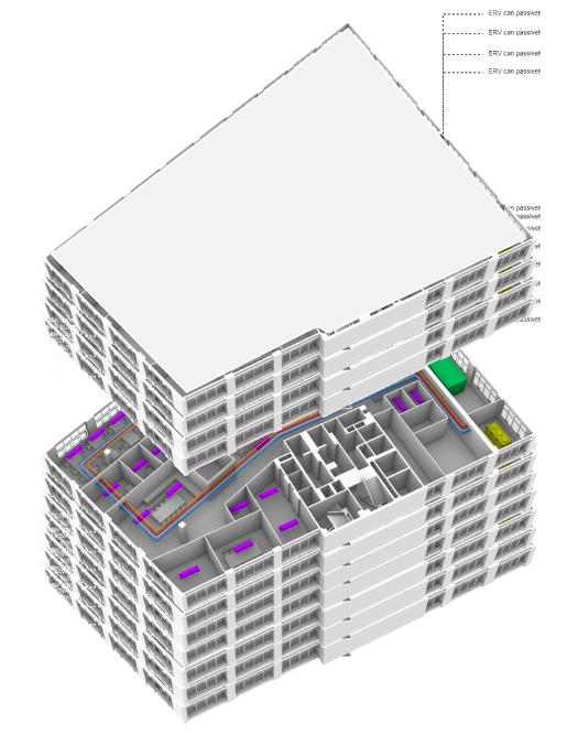 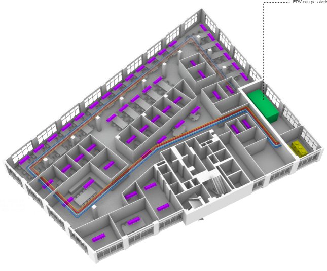
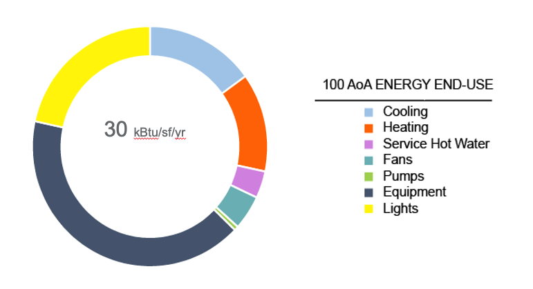
Figure - 100 AoA Building Energy Model, whole building (LEFT) vs. floor level (RIGHT) Create the Baseline Energy ModelThe baseline energy model allowed the project team to generate detailed end-use breakdown of energy usage within the building. This enabled the project team to analyze energy usage on a deeper level. For example, heating accounts for 13% of annual energy use. Looking at the equipment level, the majority of heating needs at peak heating design conditions come for the airside system, with the introduction of fresh outside air. 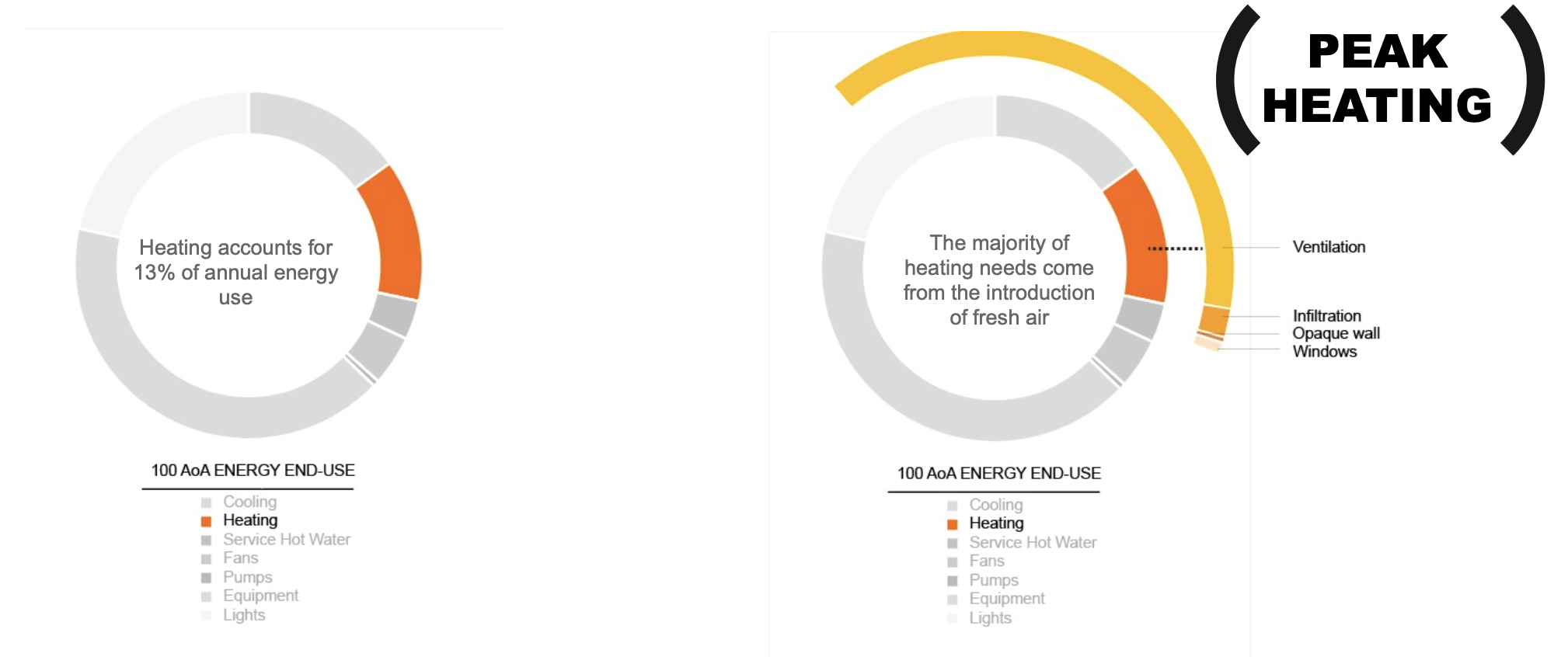
Figure - 100 AoA Heating Energy Use End-Use Breakdown Using the baseline energy model, the project team can study and understand the flow of energy within the building and as a result, identify efficiency opportunities. The illustration below shows that during much of the year, the building is heating and cooling at the same time, with core zones requiring cooling load while perimeter zones needed heat input. 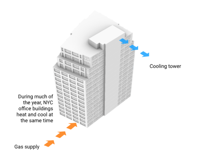 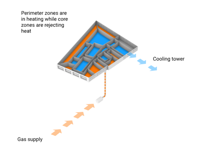
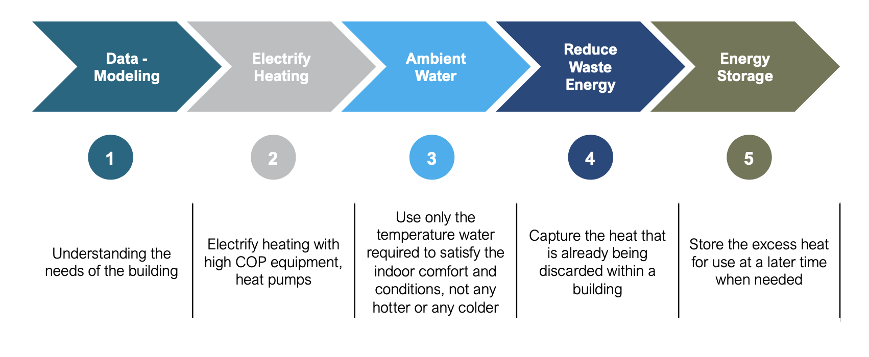
Figure - Illustration of energy flow in core and perimeter zones of the building. Analyze Individual ECMsFollowing the few simple steps shown below, the project team identified a selection of opportunities to reduce heating load and recycle wasted heat from the building. Using the baseline energy model to analyze the energy requirements and energy flows within the building, the team was able to evaluate the potential energy and carbon reduction impacts of identified measures. The project team believes that New York City's real estate industry can adopt the same circular approach to transform their aging commercial buildings to high-performing and sustainable assets. 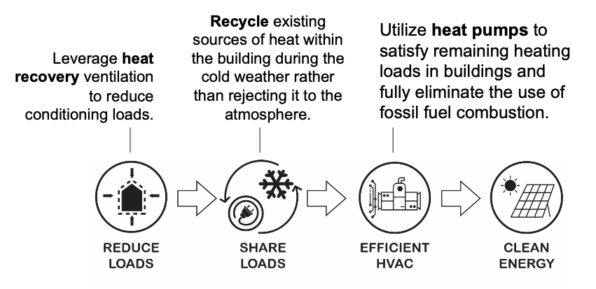
Figure - A circular approach to Commercial Office Decarbonization Reduce Loads: The analysis showed that adding a simple heat recovery wheel on the make-up air unit, the team can reduce heating loads for fresh air supply into the building by 85%. This lowers the heat load significantly by recapturing heat from the ventilation exhaust. The same analysis was performed on envelop components. Because of the small portion of heat loss due to building envelop, adding wall insulation and replacing windows were deemed not impactful. 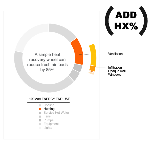 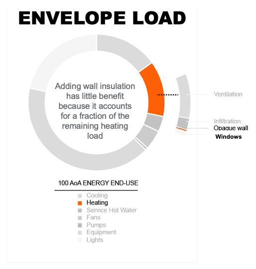
Figure - The energy impact of energy conservation measures affecting heating load: heat recovery in fresh air ventilation (LEFT) and building envelop improvements (RIGHT) Share Loads: Additionally, the analysis showed that the commercial building has simultaneous heating and cooling opportunities to implement recycling and reuse of otherwise wasted heat. The figure shown below illustrates how recapturing wasted heat from the core zones to the perimeter zones can reduce heating load significantly. 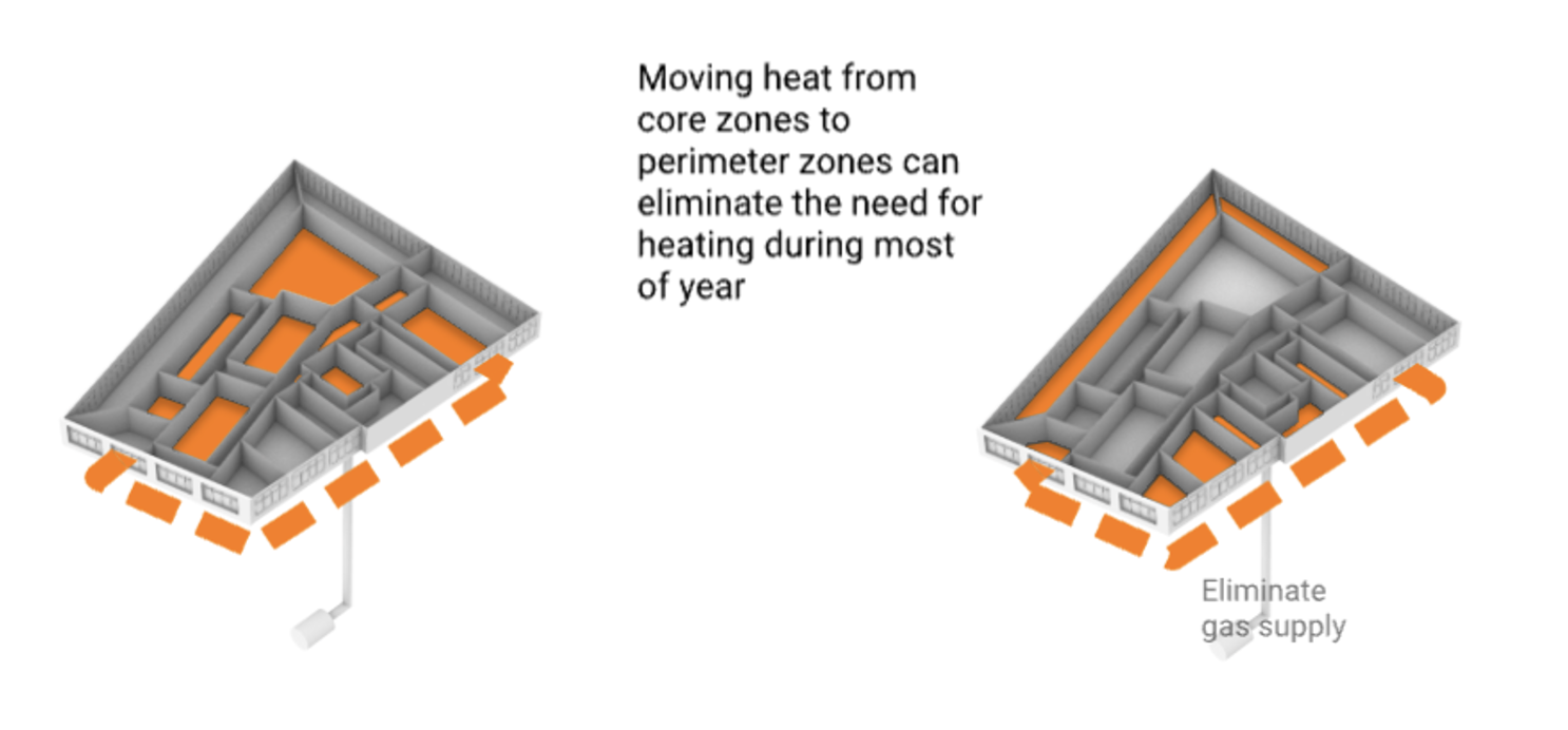
Figure - Illustration showing how recaptured heat from core zones can supply perimeter zones and reduce heating load The diagram below shows that for a particular winter design day (Feb 16 in this case), all heating load can be supplied by wasted heat from cooling exhaust. 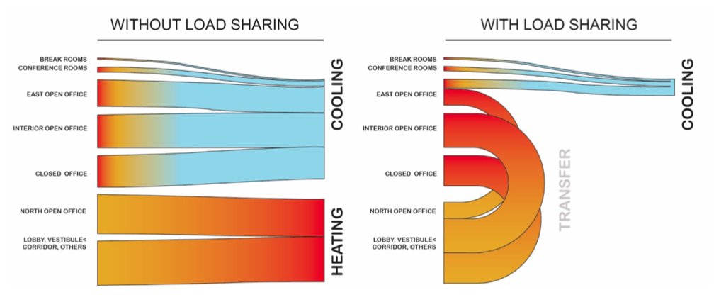
Figure - Sankey Diagram of Thermal Loads at 100 AoA for a typical winter day (modeling criteria: Feb 16, 24 hours) In summary, the analysis showed that during colder months, most of the heating need in commercial spaces is satisfied by energy from lights, people and equipment. Of the remaining mechanical temperature lift required to make a space comfortable, more than 50 percent comes from the introduction of fresh air. Rather than removing an excess of heat from interior zones, it is shifted it to perimeter spaces, which are often cooler. Fans equipped with ceramic wheels are used to recover some 90 percent of the heat in stale air being exhausted from the building. The heat is then passively transferred to incoming fresh air, which is then distributed to areas that need warming, such as those corner offices with large, inefficient windows. The heating and cooling energy is moved around through a series of water pipes, which can hold nearly six times as much energy and takes up 800 times less space than an air duct system. This reduces the amount heat needed, making it possible to warm the entire floor with low-energy electric heat pumps. Group, Sequence, and Package ECMsBased on the previous analysis, the team set out to study the following three electric-based solutions: - Option 1: A hybrid Variable Refrigerant Flow system (Hybrid VRF)
- Option 2: Active Chilled Beams with 4-Pipe Air-Source Heat Pump (4-Pipe ASHP + ACB)
- Option 3: Active Chilled Beams, 2-Pipe Air-Source Heat Pump and Thermally Activated Slab (2-Pipe ASHP + ACB + TAS)
The first two can be built with off-the-shelf parts, while the third, which has been in use in Scandinavia and Japan for more than a decade, will be available in the U.S. by 2023. All three methods rely on a single central heating/cooling machine that can transfer energy between returning hot and cold water streams simultaneously. The machines use a vapor-compression cycle, like that of a residential air conditioning unit, which runs in reverse. Rather than cooling a space by pushing heat outdoors, it transfers the heat into another area of the building that requires heat. Below is an illustration of how Option 2 and 3 would work to condition a particular floor. The Active Chilled Beam (ACB) scheme can be combined with a Thermally Activated Slab (TAS) to increase system performance. Follow the numbered descriptions below to the numbers in the diagram. - An air-to-water heat pump supplies warmed or chilled water (or both) to condition the floor plate. The heat pump has the ability to exchange heat between zones in heating and zones in cooling.
- A 4-pipe distribution system delivers the conditioned water in a loop around the floor plate. This distribution system is over seven times smaller than an equivalent air-duct would need to be to deliver the equivalent amount of conditioning to zones.
- Conditioned water circulates through active chilled beams, placed wherever heating or cooling is needed. Unlike a traditional VAV system, the active chilled beams radiate heating and cooling to occupied spaces, saving fan energy typically associated with distribution.
- Fresh air is delivered to the floor through an Energy Recovery Ventilator (ERV), capable of warming incoming fresh air with outgoing stale conditioned air. The ERV can passively reduce the need to heat incoming fresh air by up to 85%.
- The fresh air is delivered to occupied zones via ductwork connected to the active chilled beams. The ductwork is sized to move fresh air only, resulting in a significantly smaller duct system than traditional VAV.
- The scheme includes an option to embed an ambient water loop within a poured concrete floor slab. The ambient water loop can passively transfer heat from core zones in cooling to perimeter zones in heating during winter. While the scheme can work with passive chilled beams alone, this added component further reduces the work that the air-to-water heat pump needs to do.
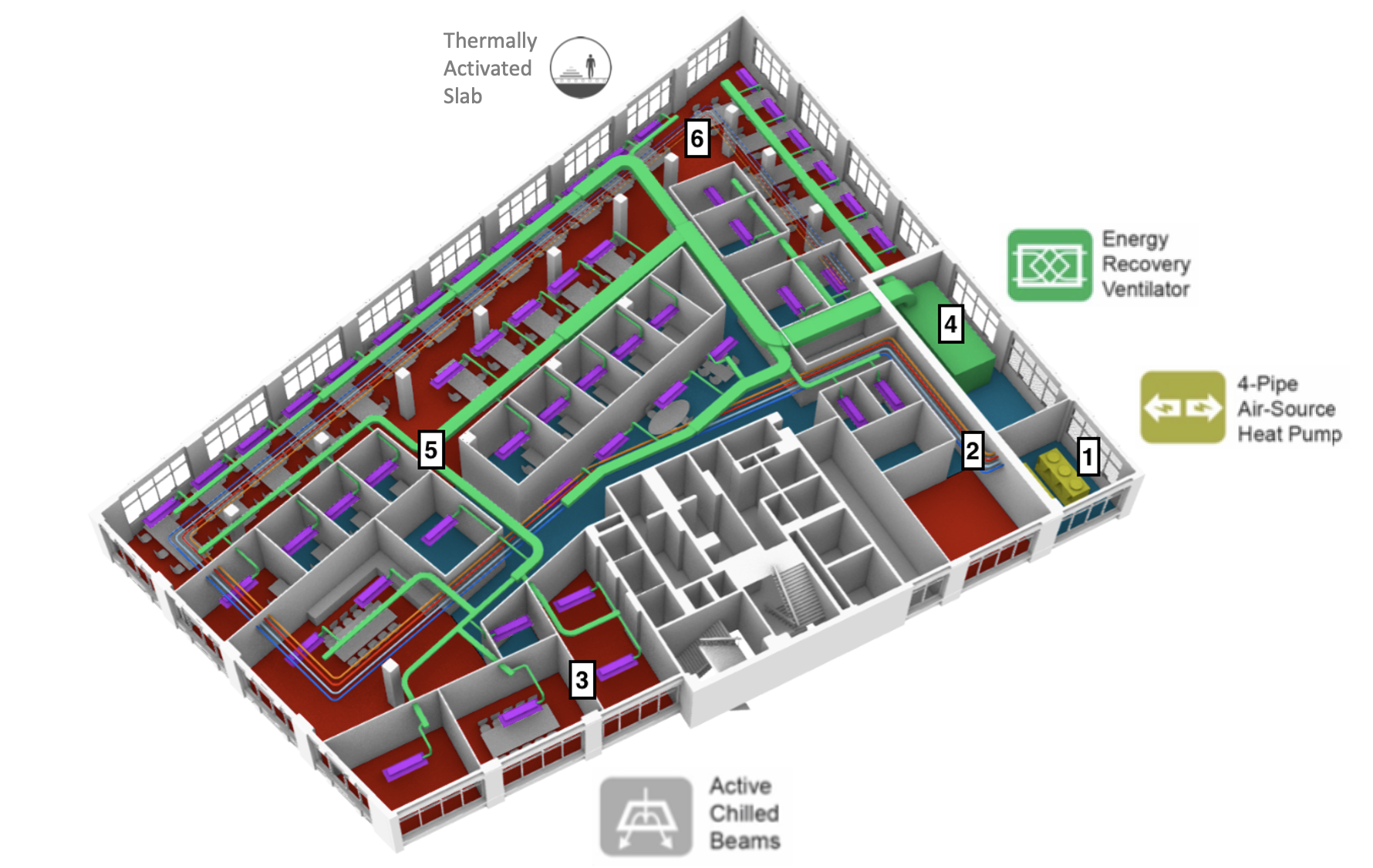
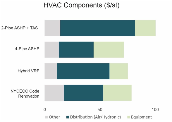
Figure - Diagram of Active Chilled Beam (ACB) and Thermally Activated Slab (TAS) Scheme The figure below shows the systems options at different system boundary condition to achieve these three packages of ECMs considered. At the floor level, you find the different combinations of decentralized heat pumps, distribution system and terminal units to supply heating and cooling to the tenants. At the building level for the landlord, you find the different options for centralized energy systems and distribution systems feeding to the tenant floors. 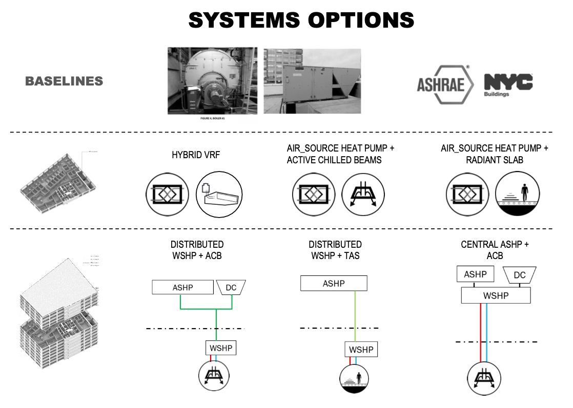
Figure - Systems options to implement packaged solutions Ambient Loop with Energy Arbitrage: One of the last steps to enable heat sharing between zones and floors via heat pumps and chillers is to lower the water temperature in the distribution system. The condenser water loop when connected to all floor level Heat Pumps will start allowing the rejected energy to be used by floors in need of heating. For 44% of the time, the tenant spaces require simultaneous heating and cooling. The system will keep the exhausted energy to minimum with using water as a medium and allowing waste heat from one floor to become an energy source for the other. The loop will also adjust itself with the ambient temperatures and allow the system to become a true open system where energy and mass can exchange. The project team calls it Ambient Loop and the exchange as Energy Arbitrage. 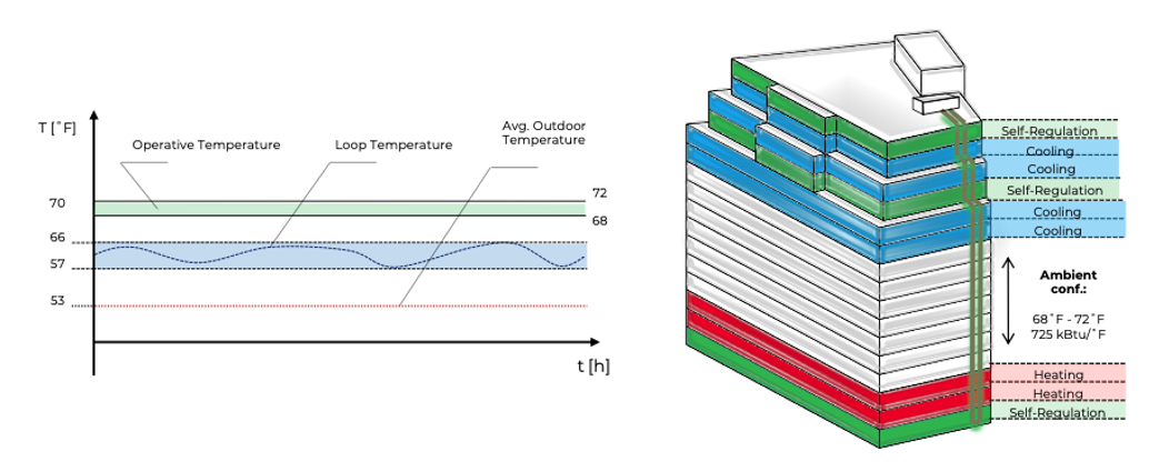
Figure - Ambient Loop Concept with Energy Arbitrage Phased Implementation: An important aspect of the decarbonization roadmap is to define the implementation approach to minimize construction time and tenant disruption. In this case, the new systems can be phased in over time. Rather than retrofitting the entire building, work can be done on a floor-by-floor basis, which is easier on the budget, allows for greater scheduling flexibility and is less disruptive to existing tenants. It is estimated that full-floor tenants vacate spaces every 10 to 15 years, providing ample opportunities for upgrades before the city’s 2050 deadline. Generate a Decarbonization RoadmapNow that the packaged ECMs have been defined, the energy model can be run for each options to evaluate energy and carbon impacts. The three proposed packaged solution results were compared to the baseline condition and the minimum building code scenario (following the 2020 NYCECC energy conservation construction code). The analysis generated the following results: 40 to 60% reduction in energy usage and no on-site use of fossil fuel. Option 3, with the combination of active chilled beams and radiant floors yielded the most savings (58%) and the lowest EUI (< 30 kBtu/sf/yr). 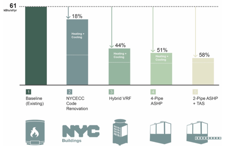
Figure - ECM Packages Energy Savings Comparison The carbon impact of these packages were also analyzed. The results displayed in the figure below shows how Option 2 and 3 can significantly reduce carbon emissions in both winter and summer scenario. 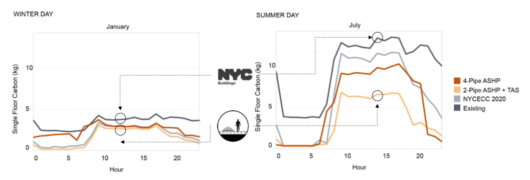
Figure - ECM Packages Carbon Savings Comparison for both a typical winter day (LEFT) and summer day (RIGHT) The results for all of the options were better than expected: load sharing is not only possible but could virtually eliminate the need for gas heating in New York’s buildings, making decarbonization possible. Unlike combustion or electric resistance, the systems output more energy than they use. A large scale heat pump can achieve efficiencies of 200% to 300% in standalone heating or cooling mode and efficiencies of 500% to 700% when simultaneous loads allow for energy sharing. Back to Table of Contents | 


